WhisperGreen Select Wiring Configurations
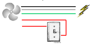
Method 1: Manual Control Wiring Diagram (ON/OFF or boost from low speed to high speed)
-
Bring power from the source directly to the fan junction box.
-
Bring the black conductor to the power lead for the fan motor.
-
Bring the white wire to the white lead in the fan junction box.
-
Attach the bare ground wire to the green wire in the fan junction box.
-
The red wires are not designed to carry current. Do not attach these to power. They are signal wires that are used to turn the fan from standby to 'on' or from low to high speed if using the continuous run module.
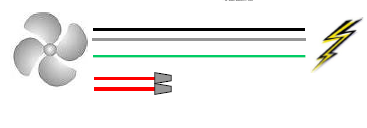
Method 2: Automatic Control Wiring Diagram (wire direct to the power supply)
-
Bring power from the source directly to the fan junction box.
-
Bring the black conductor to the power lead for the fan motor.
-
Bring the white wire to the white lead in the fan junction box.
-
Bring the bare ground wire to the green wire in the fan junction box.
-
Leave the red wires capped separately and tucked into the junction box.
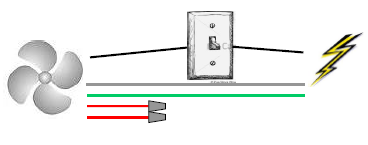
Method 3: Basic Wiring Diagram (ON/OFF for single speed)
-
Bring power from the panel to a wall switch.
-
At the wall switch, attach the black cable at the line side of a single-pole switch.
-
Have the black cable connected to the load side of the switch up into the fan junction box connected to the black conductor from the fan motor.
-
Have the white cables connect together at the switch box and continue to the junction box where it is conducted to the white lead in the junction box.
-
The ground wires are brought up to the wall switch and continue up to the ground lead, the green wire, from the junction box.
-
The two red wires remain untouched.